Finally, some pictures and a video clip.
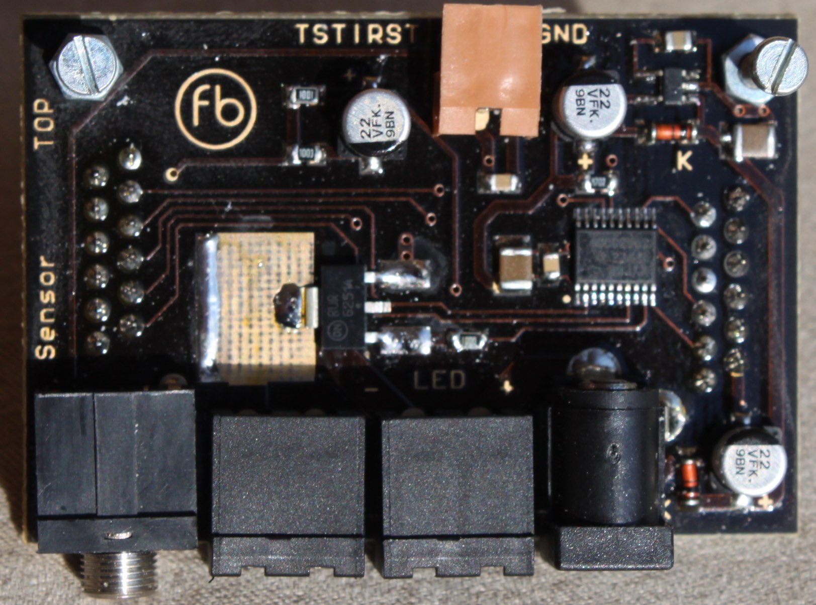
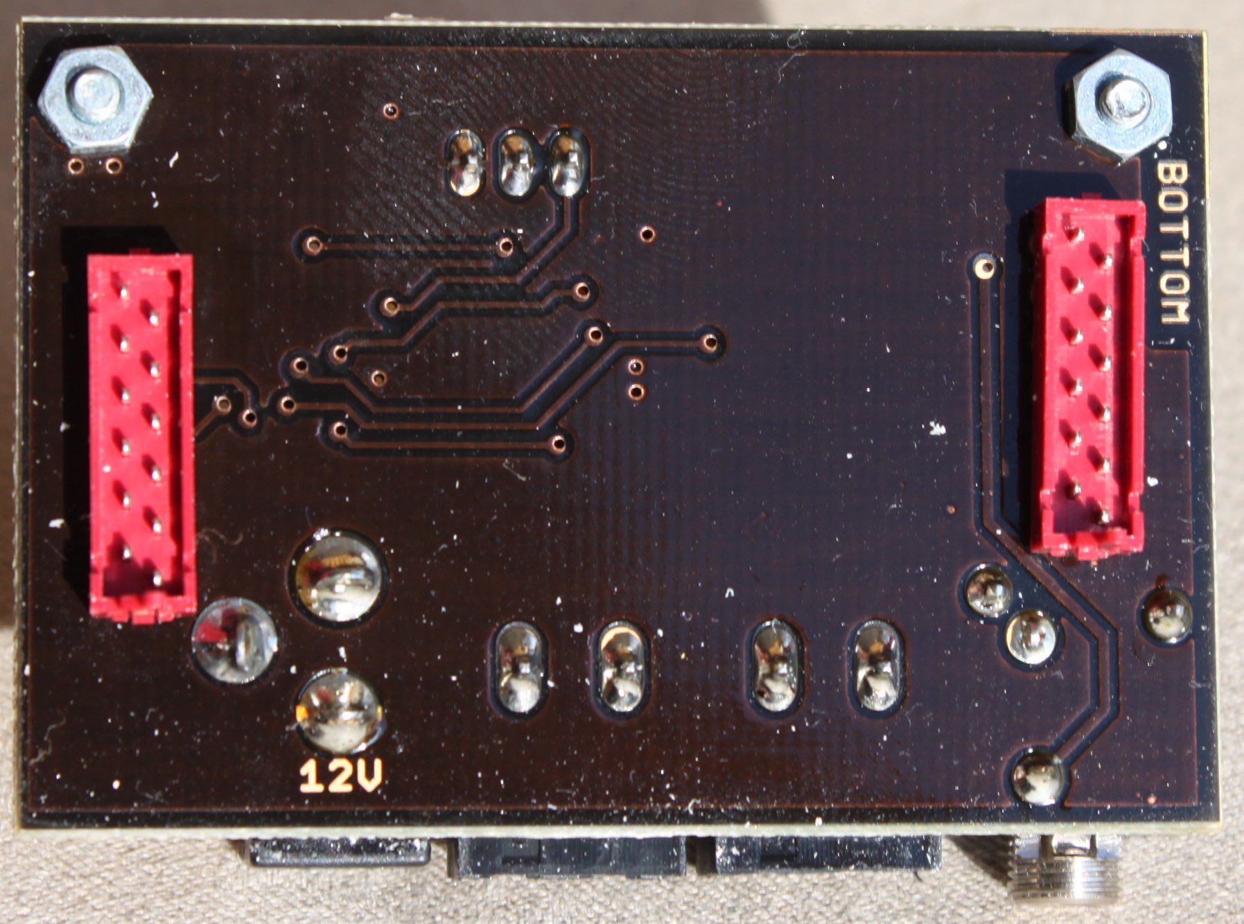
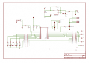
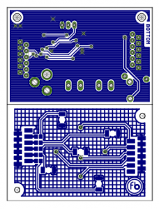
The main PCB:
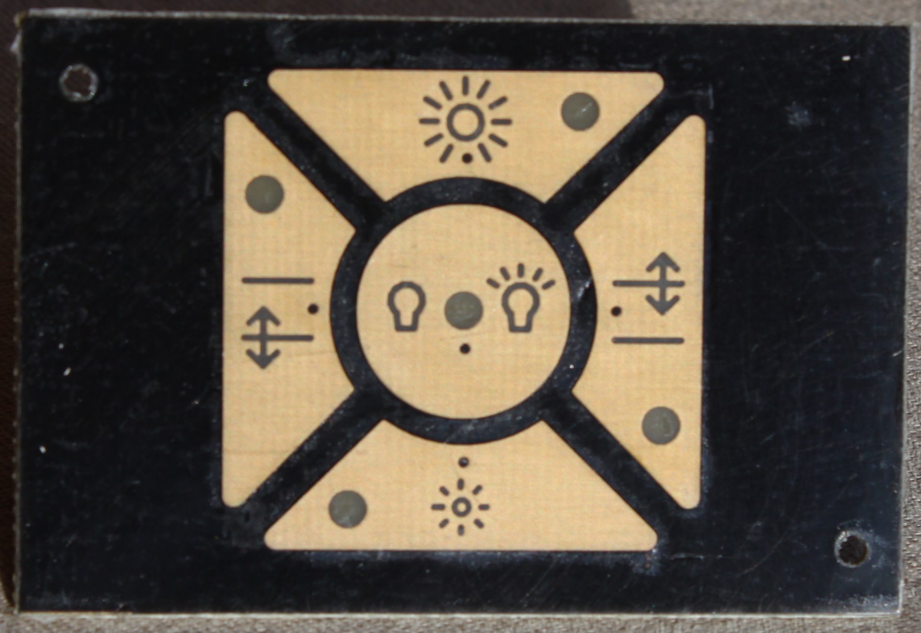
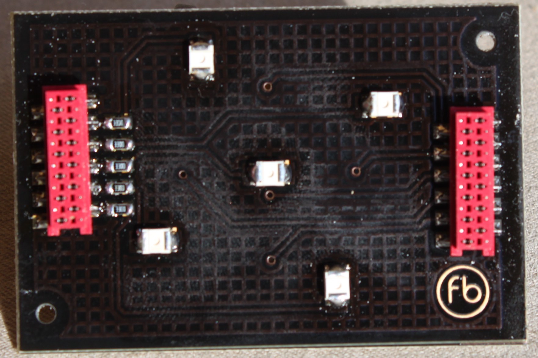
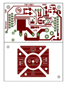
The touch PCB:
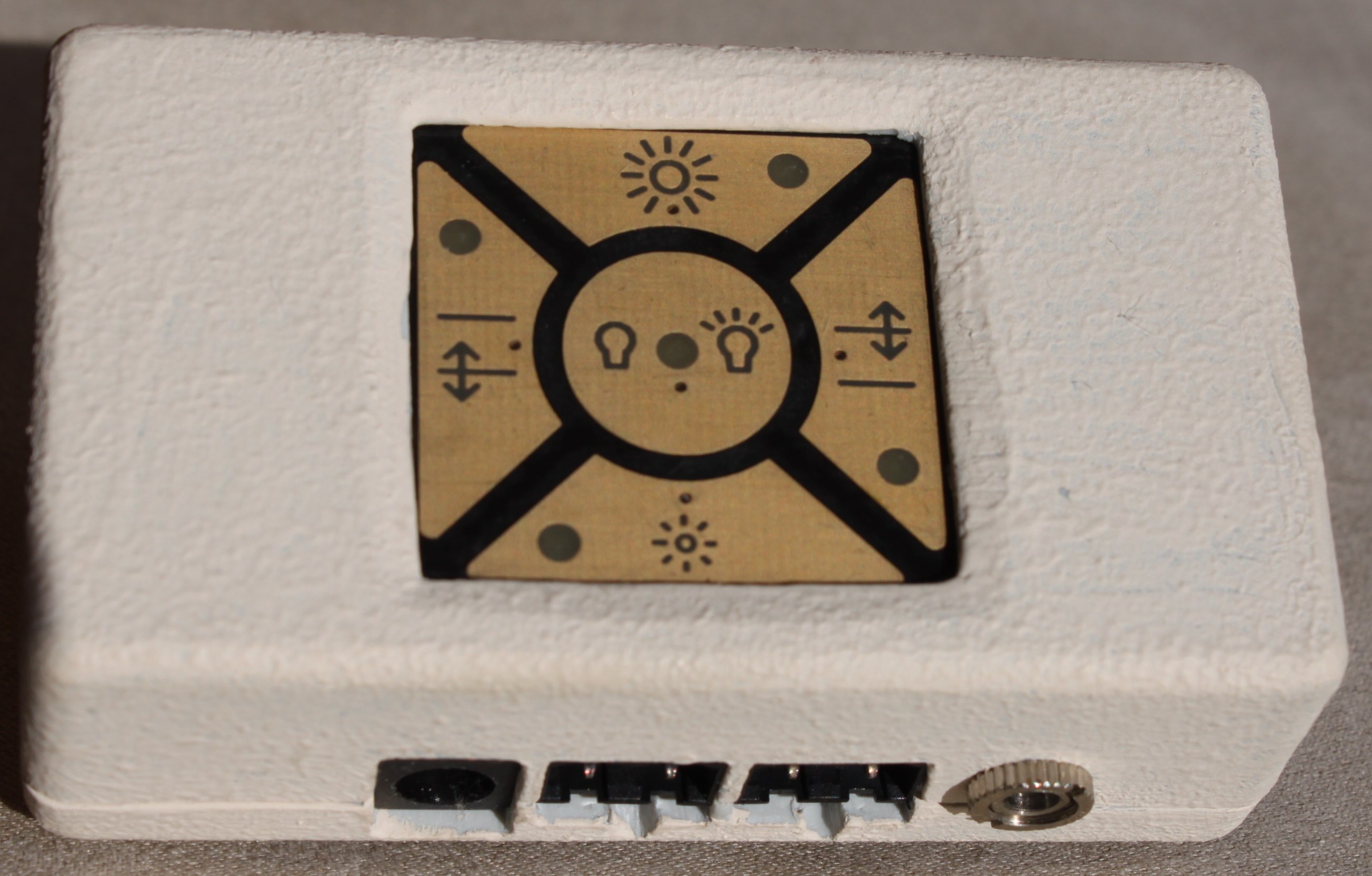
Completed:
Function video clip:
Things I want to share

Finally, some pictures and a video clip.
The main PCB:
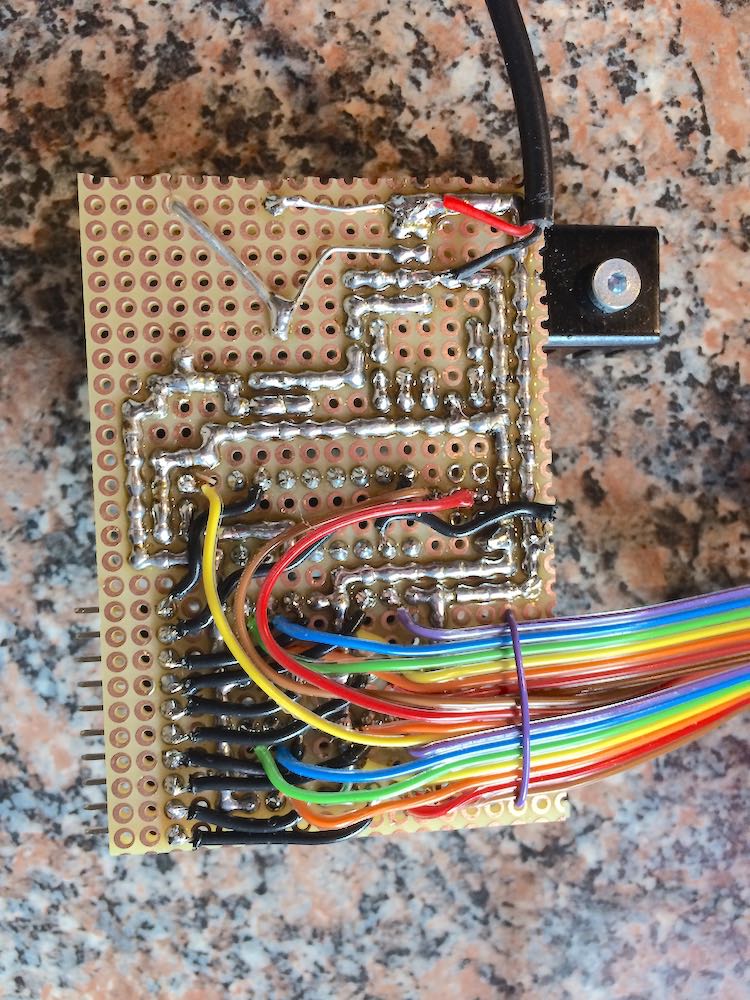
The touch PCB:
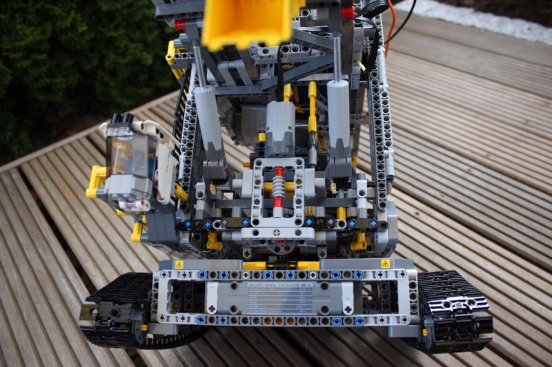
Completed:
Function video clip:
The circuit of the control unit for my showcase lighting is very simple. The core is the microcontroller MSP430G2553. A linear voltage regulator generates the required 3.3 V. The board has 2 connections for LED strips that are driven by a MOSFET. The brightness information is passed on to the ADC of the controller with a photoresistor and is evaluated there. Most I/O of the controller are required for the 5 capacitive touch fields and the feedback LEDs.
Dimming is done by PWM.
Assignment of the 5 touch fields:
This should have stand at the beginning:
There is another reason why I was so eager for the bucket wheel excavator. I live in a former surface mining area and an original bucket wheel excavator stands in the middle of a field near my home.
 Bucket wheel excavator type SRs 1500
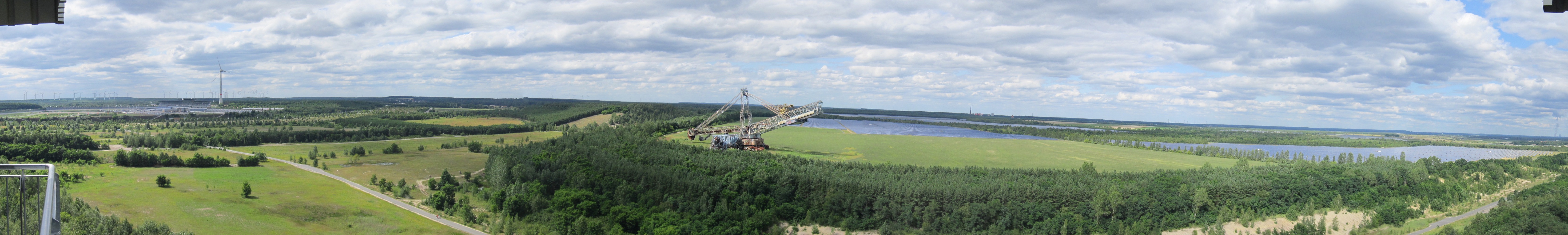
Panoramic view from left:
And: I got a blog entry at hackaday.com. 🙂
I would like to have a solution for my showcase lighting which is small, simple, inconspicuous, but chic.
There are 2 showcases to be illuminated. LED strips are already installed in the showcases, once 2 and once 3. The strips are operated with 12V. The power is about 3Wmax per strip. For 5 strips, this is 1.25 A, which is not to much. In addition, this is much too bright and will probably be operated mostly dimmed.
Power supply is a 12 V plug-in power supply. To build something by myself is not necessary.
Since I like to try other things, I did not take an Arduino, but a TI MC of the type MSP430G2553. For development, I got the launchpad MSP-EXP430G2 , which already brings the programming interface for programming my own board later. At the same time I didn’t want any buttons and found the idea of capacitive switch fields very elegant. The MSP430 Capacitive Touch BoosterPack is compatible with the Launchpad.
There are Code Composer Studio builds for Windows, MacOS and Linux, however, the MSP-EXP430G2 is not supported in MacOS, so I had to take the Windows version🙁.
Perhaps you know this too: You have finally decided for a new living room furniture and maybe this includes also a glass showcase. If that would be illuminated … (I know, this is old-fashioned (or a matter of taste)).
Something like this is well-known for a long time. Problem with this: with normal incandescent light it is expensive and if you have to switch on the lighting manually, you will not do it anyway.
Today, LED strips are used. A problem remains: manual switch-on is uncomfortable.
I faced this problem a while ago.
The available automatics were expensive and / or crap and did not what I wanted anyway.
I don’t want to have to worry about this lighting again after I first switched it on, if I don’t want to.
The following characteristics are important to me:
The next contributions show how I solved the challenge.
Here in advance the original and the finished modification. an important goal was to keep the excavator as original as possible.
 original version
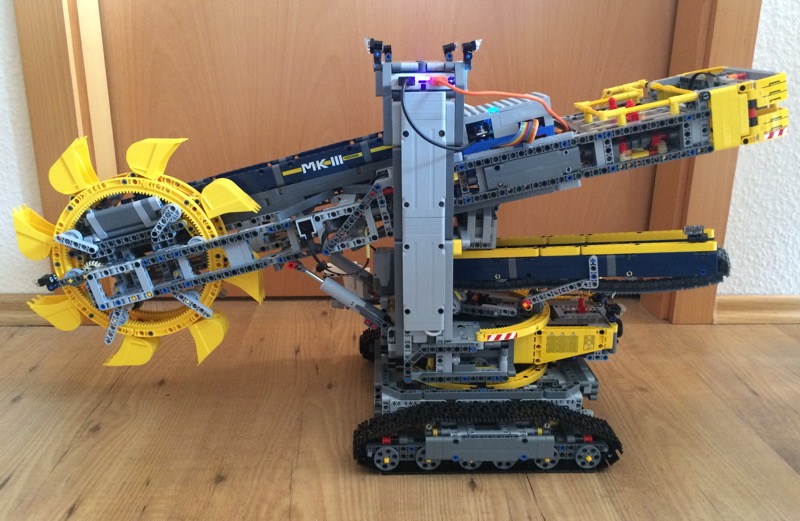 finished modification
Details of the mdificationo will follow later.
Essentially, the project consists of three parts:
As mentioned earlier, the goal was to make the modifications with as few changes aspossible. Nevertheless, this is not gone without additional parts.
I ordered the 4 M-motors as well as the leads directly at Lego.com. All other parts were from KieselBrick over Brickscout , which I can absolutely recommend.
Unfortunately, I cannot provide an exact part list, since I have selected the parts ad hoc and could also reuse many parts, which were left by the modifications before.
The original is driving, but only straight ahead, no steering is available. In addition, the engine sits at the top of the main transmission. That is why I have installed 2 M motors below, which are controllable separately. The inspiration got here , but ultimately I have built my own variant, which seems to be a bit easier to me.

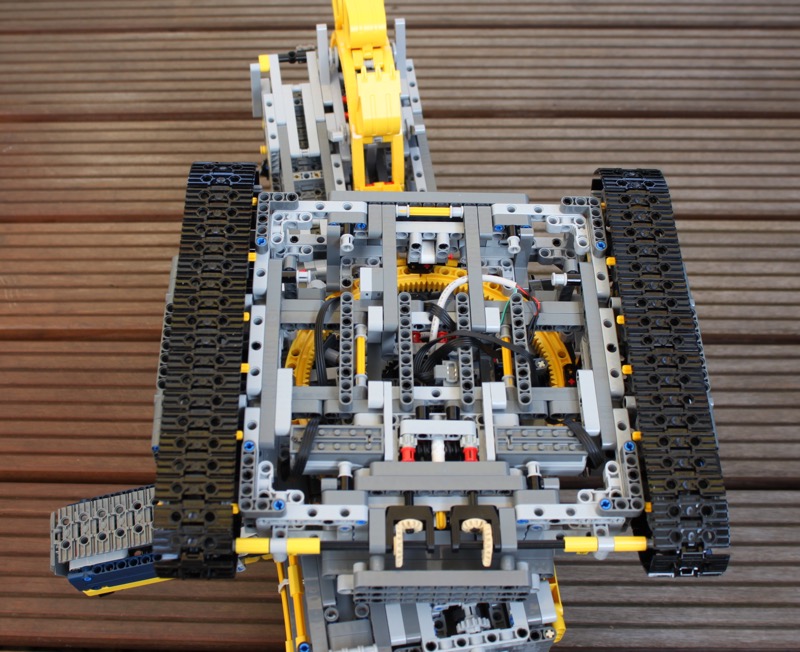
The cable to the motors I have centrally guided over the axis of rotation, so a turning of the tower is still possible.
Originally, the turning of the tower is also solved by the gearbox with the XL motor. I separated the connection between gearbox and linkage and inserted at this point an M-Motor with a worm wheel.
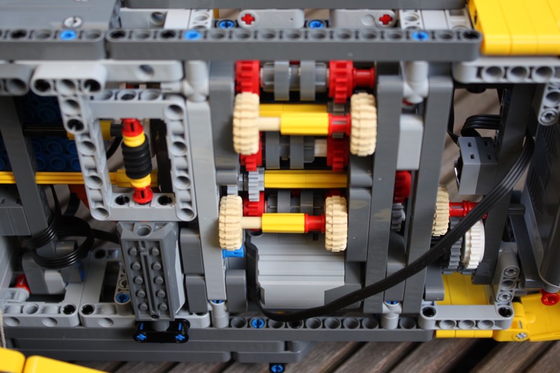
The lifting and lowering of the bucket wheel is originally only possible manually. But here it is also very easy to use an M-motor with a worm wheel.
Remains the drive of the bucket wheel and the conveyor belts: I left it as it is. The XL engine does it quite nice. The last degree of freedom, the turning of the small conveyor belt, I left unchanged.
Before I describe the board itself, a few words about the battery.
As a rechargeable battery a Powerbank is used. One with 2 USB ports, one for the Raspberry Pi and one for the motors. The form factor should be such that it can be easily installed. I choosed a flat square shaped type that has a high-power output. This is important, as the motors demand a relevant current (details can be googled). Unfortunately, that was not enough. The battery reacts very sensitive to the starting current of the motors, ie the overcurrent protection often turned off the battery, which was quite annoying. Luckily I have found another battery with similar dimensions and a little more nominal current rating. This here is it, however, nobody knows how it will be available …
I need:
For the motor control of the M motors I use the L293D, a robust, proven DC motor driver, the version with the integrated diodes.
Since the XL motor does not need a reversing of the direction of rotation, a relay is sufficient, I use a DIL14 reed relay (type 3570-1210-053, 5V) with 0.5A switching current.
The step-up converter is an LM2577-ADJ, robust technology, slightly oversized, no problems expected.
An RGB status LED, ready.
As a housing for the Raspberry Pi I took a Lego-compatible case. The board is to fit exactly so that it can be installed with Lego parts. The following pictures show the solution.
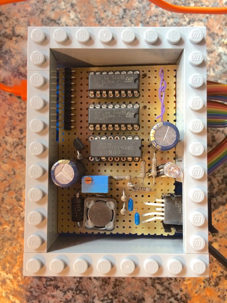
As already mentioned, the heart is a Raspberry Pi 3. The built-in Bluetooth module is handy and can be paired with a Wiimote.
Operating system is the current Raspbian, and Python version 2.x is used, since the used Wiimote library does not work with version 3.x.
Ah yes, a tutorial about how to install the library and how to connect the Wiimote is available on this page , for example. Of course, with the Pi 3 you can skip the installation of a Bluetooth dongle.
Here is a section of the Python program:
 while True:

    buttons = wii.state['buttons']

  #Achtung: WiiMote wird quer gehalten, deshalb RIGHT --> Vorwaerts
    if(buttons & cwiid.BTN_RIGHT):
      if(buttons & cwiid.BTN_DOWN):     #DOWN --> rightfor
        Drive_rightfor()
      elif(buttons & cwiid.BTN_UP):     #UP --> leftfor
        Drive_leftfor()
      else:
        Drive_forward()
    elif(buttons & cwiid.BTN_LEFT):     #LEFT --> Rueckwaerts
      if(buttons & cwiid.BTN_DOWN):     #DOWN --> rightback
        Drive_rightback()
      elif(buttons & cwiid.BTN_UP):     #UP --> leftback
        Drive_leftback()
      else:
        Drive_back()
    else:
      if(buttons & cwiid.BTN_UP):       #UP --> leftturn
        Drive_leftturn()
      elif(buttons &cwiid.BTN_DOWN):    #DOWN --> rightturn
        Drive_rightturn()
      else:
        Drive_stop()
    time.sleep(0.1)

#Turm drehen mit 1 und 2
    if(buttons & cwiid.BTN_1):
      Turn_left()
    elif(buttons & cwiid.BTN_2):
      Turn_right()
    else:
      Turn_stop()
    time.sleep(0.1)

#Turm heben mit + und -
    if(buttons & cwiid.BTN_PLUS):
      Lift_up()
    elif(buttons & cwiid.BTN_MINUS):
      Lift_down()
    else:
      Lift_stop()
    time.sleep(0.1)

#Band und Bagger
    if(buttons & cwiid.BTN_A):
      if(pressed == '0' and run == 'stop'):
        Band_run()
        pressed = 'A'
      elif(pressed == '0' and run == 'run'):
        Band_stop()
        pressed = 'A'
    else:
      pressed = '0'

    time.sleep(0.1)

....
And here is the layout of the Wiimote:
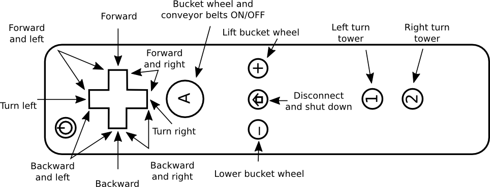
Because no monitor and no keyboard will be plugged into the Pi, the program must start automatically. The Status LED, which is always blue when power is on, flashes red briefly when the Wiimote can be paired (simultaneous pressing 1 and 2). If the pairing is successful, the green LED is additionally lit.
If the pairing is unsuccessful, the program terminates, but Pi remains on.
After the pairing has been completed, you can play with the excavator.
If you have finished, separate the Wiimote with the Home button. Then the Pi shut down. Holding the B button (on the back) while pressing Home will close the connection. The Pi does not shut down.