Before I describe the board itself, a few words about the battery.
As a rechargeable battery a Powerbank is used. One with 2 USB ports, one for the Raspberry Pi and one for the motors. The form factor should be such that it can be easily installed. I choosed a flat square shaped type that has a high-power output. This is important, as the motors demand a relevant current (details can be googled). Unfortunately, that was not enough. The battery reacts very sensitive to the starting current of the motors, ie the overcurrent protection often turned off the battery, which was quite annoying. Luckily I have found another battery with similar dimensions and a little more nominal current rating. This here is it, however, nobody knows how it will be available …
I need:
- 4 x motor control with change of direction for the 4 M motors
- 1 x simple motor control for the XL motor
- Step-up converter to provide the 9V from 5V
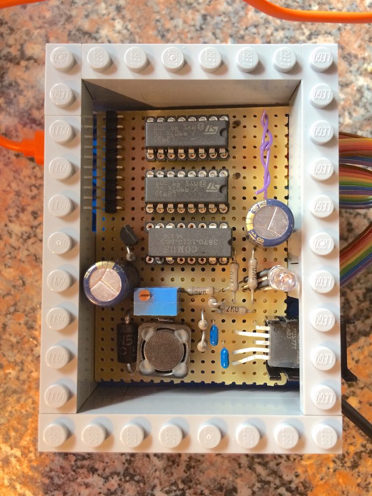
For the motor control of the M motors I use the L293D, a robust, proven DC motor driver, the version with the integrated diodes.
Since the XL motor does not need a reversing of the direction of rotation, a relay is sufficient, I use a DIL14 reed relay (type 3570-1210-053, 5V) with 0.5A switching current.
The step-up converter is an LM2577-ADJ, robust technology, slightly oversized, no problems expected.
An RGB status LED, ready.
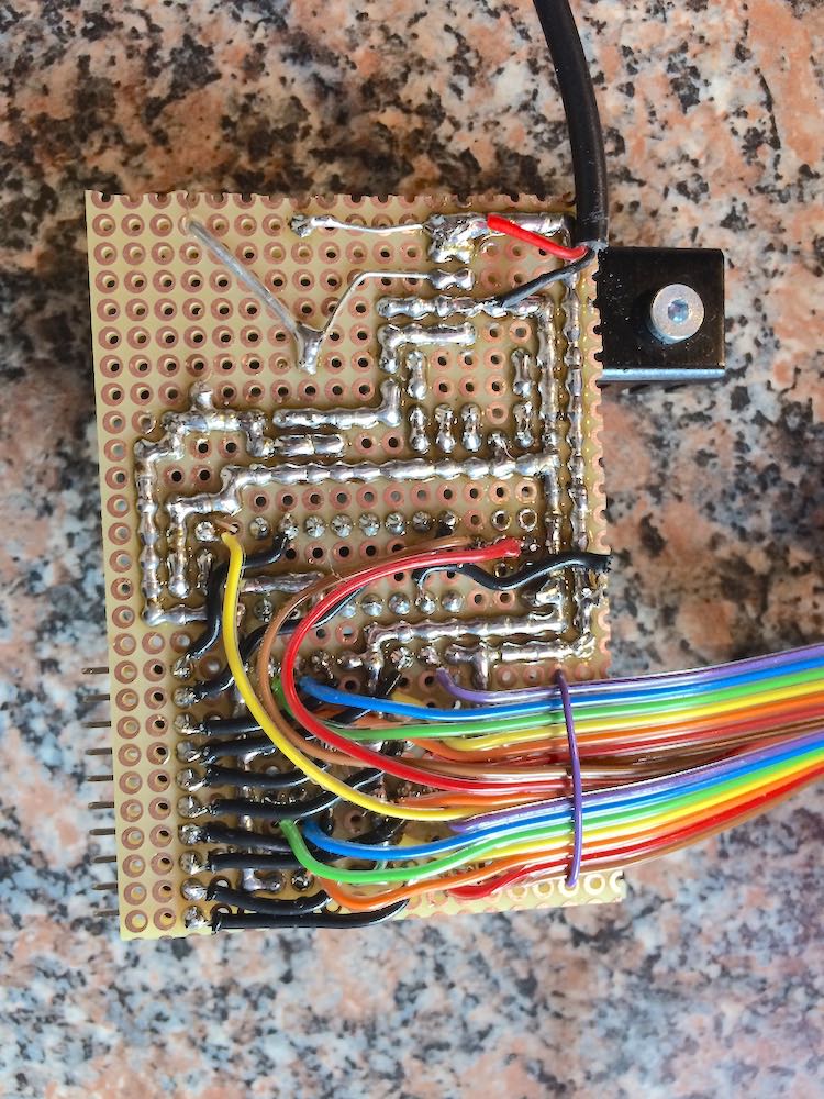
As a housing for the Raspberry Pi I took a Lego-compatible case. The board is to fit exactly so that it can be installed with Lego parts. The following pictures show the solution.